Design Guidelines: Overmolding & Insert Molding
Our basic guidelines for overmolding and insert molding include important design considerations to help improve part manufacturability, enhance cosmetic appearance, and reduce overall production time.
Size
Maximum Dimensions
| SIZE | 18.9 in. x 29.6 in. x 8 in. |
|---|---|
| VOLUME | 59 cu. in. |
| DEPTH | 4 in. from parting line |
| Up to 8 in. if the parting line can pass through the middle of the part | |
| PROJECTED MOLD AREA | 175 sq. in. (plastic) 48 sq. in. (silicone rubber) |
| SIZE | 480mm x 751.8mm x 203.2mm |
|---|---|
| VOLUME | 966837 cu. mm |
| DEPTH | 101mm from parting line |
| Up to 203.2mm if the parting line can pass through the middle of the part | |
| PROJECTED MOLD AREA | 112903 sq. mm (plastic) 30968 sq. mm (silicone rubber) |
Height may be limited if using a silicone as the overmold material, and deeper parts are limited to a smaller outline. Minimum part volume is 0.025 cu. in. (40.98 cu. mm). With substrate molds, we can maintain a machining tolerance of ±0.003 in. (0.08mm) with an included resin tolerance that can be greater but no less than 0.002 in./in. (0.002mm/mm). With thermoplastic overmolds, tolerances remain the same as substrate molds, however, if the overmold is LSR, then tolerances shift to 0.025 in./in. (0.025mm).
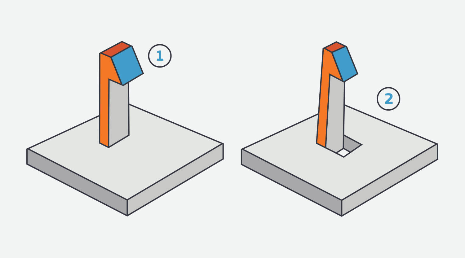
Insert Molding Capabilities
Instead of a mold that produces a final part using two separate shots like overmolding, insert molding generally consists of a preformed part—often metal—that is loaded into a mold, where it is then overmolded with plastic to create a part with improved functional or mechanical properties. We currently accept inserts from PEM, Dodge, Tri-Star, Spirol, and Tappex. A complete chart of stocked inserts at Brazil Metal Parts is available here.
One way insert molding is used is with threaded inserts, which reinforce the mechanical properties of plastic parts’ ability to be fastened together, especially over repeated assembly. Bushings and sleeves are another great way to increase part durability for mating components that need more abrasion resistance due to moving parts.
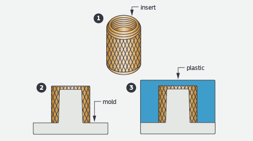
A threaded insert is placed atop a mold core where plastic is molded over it to form the final component.

Materials
- ABS
- Acetal
- HDPE
- LCP
- PEI
- PMMA
- Polycarbonate
- Polypropylene
- PPA
- PPS
- PS
- PS
- PSU
- TPE
- TPU
- PEEK
- Liquid Silicone Rubber
Overmolding Material Bonding
Chemical bonding between overmolded materials is possible, but material compatibility should be considered in order to achieve desired bond strength. Incorporation of an adequate mechanical bond is strongly recommended if bonding is critical to your application. An undercut is a good example of a mechanical bond.
| Substrate Material | ||||||
|---|---|---|---|---|---|---|
| Overmold Material | ABS Lustran | ABS/PC CYCOLOY C2950-111 | PC Lexan 940-701 |
PBT Valox 357-1001 |
PP Profax 6323 | |
| TPU - Texin 983-000000 |
C | C | C | C | M | |
| TPV - Santoprene 101-87 |
M | M | M | M | C | |
| TPE - Santoprene 101-64 |
M | M | M | M | C | |
| LSR - Elastosil 3003/30 A/B |
- | - | M | M | - | |
| TPC - Hytrel 3078 | C | C | C | C | M | |
| TPE-Versaflex OM 1060X-1 |
C | C | C | M | M | |
| TPE-Versaflex OM 6240-1 |
M | M | M | M | M | |
| TPE-Versaflex OM 6258-1 |
M | M | M | M | M | |
| TPE-Versaflex OM 1040X-1 |
C | C | C | M | M | |
M = mechanical bond (recommended)
C = chemical bond

Surface Finishes
| FINISH | DESCRIPTION |
|---|---|
| PM-F0 | non-cosmetic, finish to Brazil Metal Parts' discretion |
| PM-F1 | low-cosmetic, most toolmarks removed |
| PM-F2 | non-cosmetic, EDM permissible |
| SPI-C1 | 600 grit stone, 10-12 Ra |
| PM-T1 | SPI-C1 + light bead blast |
| PM-T2 | SPI-C1 + medium bead blast |
| SPI-B1 | 600 grit paper, 2-3 Ra |
| SPI-A2 | grade #2 diamond buff, 1-2 Ra |
Draft
| VERTICAL FACES | 0.5° |
|---|---|
| MOST SITUATIONS | 2° |
| MINIMUM FOR SHUT OFF | 3° |
| MINIMUM FOR LIGHT TEXTURE (PM-T1) | 3° |
| MINIMUM FOR LIGHT TEXTURE (PM-T2) | 5°+ |
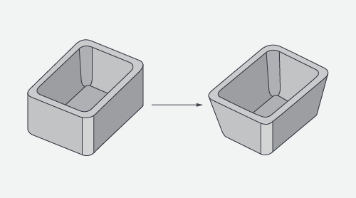
Adding draft angles to design helps facilitate ejection of a part from a mold, and improves overall moldability.
Undercuts
Maximum Side Core Dimensions
| WIDTH | HEIGHT | PULL |
|---|---|---|
| < 8.419 in. | < 2.377 in. | < 2.900 in. |
| WIDTH | HEIGHT | PULL |
|---|---|---|
| <213.84mm | <60.38mm | <73.66mm |
Wall Thickness
| MATERIAL | RECOMMENDED WALL THICKNESS |
|---|---|
| ABS | 0.045 in. - 0.140 in. |
| Acetal | 0.030 in. - 0.120 in. |
| Acrylic | 0.025 in. - 0.500 in. |
| Liquid Crystal Polymer | 0.030 in. - 0.120 in. |
| Long-Fiber Reinforced Plastics | 0.075 in. - 1.000 in. |
| Nylon | 0.030 in. - 0.115 in. |
| Polycarbonate | 0.040 in. - 0.150 in. |
| Polyester | 0.025 in. - 0.125 in. |
| Polyethylene | 0.030 in. - 0.200 in. |
| Polyphenylene Sulfide | 0.020 in. - 0.180 in. |
| Polypropylene | 0.035 in. - 0.150 in. |
| Polystynene | 0.035 in. - 0.150 in. |
| Polyurethane | 0.080 in. - 0.750 in. |
* The table is adapted from manufacturingcenter.com.
|
MATERIAL |
RECOMMENDED WALL THICKNESS |
|---|---|
| ABS | 1.143mm - 3.556mm |
| Acetal | 0.762mm - 3.048mm |
| Acrylic | 0.635mm - 12.7mm |
| Liquid Crystal Polymer | 0.762mm - 3.048mm |
| Long-Fiber Reinforced Plastics | 1.905mm - 25.4mm |
| Nylon | 0.762mm - 2.921mm |
| Polycarbonate | 1.1016mm - 3.81mm |
| Polyester | 0.635mm - 3.175mm |
| Polyethylene | 0.0762mm - 5.08mm |
| Polyphenylene Sulfide | 0.508mm - 4.572mm |
| Polypropylene | 0.635mm - 3.81mm |
| Polystynene | 0.89mm - 3.81mm |
| Polyurethane | 2.032mm - 19.05mm |
* The table is adapted from manufacturingcenter.com.
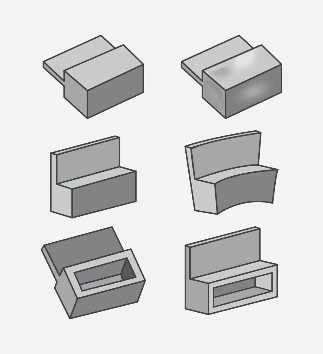
The top row represents a part designed with thick features and the resulting sink once molded. The middle row also shows a part designed with thick features, but this time the warp that occurs once molded. The bottom row demonstrates how coring out thick features helps create an optimally molded part.
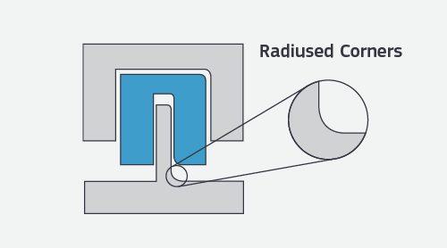
Radii
Some part corners will have a radius rather than a sharp edge since we use an automated CNC milling process to make the mold for your parts. This typically does not require a change to your model, but resulting radii are identified before the mold is milled.

Free moldability analysis within hours
GET A QUOTERequest More Information
Thanks! We’ve received your message and a member of our team will be in touch with you shortly.
You can find more information about Brazil Metal Parts here:
Thanks for your interest in Brazil Metal Parts. Please let us know how we can provide more information on our services. Once we receive your comments, an applications engineer from our team will follow-up as soon as possible.
If you have a 3D CAD model of your part ready, upload it online now to receive an interactive quote with free design for manufacturability feedback within hours.