Design Guidelines: Stereolithography (SLA)
Our basic guidelines for stereolithography include important design considerations to help improve part manufacturability, enhance cosmetic appearance, and reduce overall production time.
Size
Maximum Dimensions
| NORMAL RESOLUTION | 29 in. x 25 in. x 21 in. |
|---|---|
| HIGH RESOLUTION | 10 in. x 10 in. x 10 in. |
| MICRO RESOLUTION | 5 in. x 5 in. x 2.5 in. |
| NORMAL RESOLUTION | 736mm x 635mm x 533mm |
|---|---|
| HIGH RESOLUTION | 254mm x 254mm x 254mm |
| MICRO RESOLUTION | 127mm x 127mm x 63.5mm |
Accuracy
Layer Thickness
| NORMAL RESOLUTION | 0.004 in. |
|---|---|
| HIGH RESOLUTION | 0.002 in. |
| MICRO RESOLUTION | 0.001 in. |
| NORMAL RESOLUTION | 0.1016mm |
|---|---|
| HIGH RESOLUTION | 0.0508mm |
| MICRO RESOLUTION | 0.0254mm |
Minimum Feature Size
| NORMAL RESOLUTION | 0.010 in. for the XY draw plane (0.016 in. for the Z build direction) |
|---|---|
| HIGH RESOLUTION | 0.005 in. for the XY draw plane (0.016 in. for the Z build direction) |
| MICRO RESOLUTION | 0.0025 in. for the XY draw plane (0.008 in. for the Z build direction) |
| NORMAL RESOLUTION | 0.254mm for the XY draw plane (0.406mm for the Z build direction) |
|---|---|
| HIGH RESOLUTION | 0.1016mm for the XY draw plane (0.406mm for the Z build direction) |
| MICRO RESOLUTION | 0.0508mm for the XY draw plane (0.203mm for the Z build direction) |
For well-designed parts, tolerances in the X/Y dimension of ±0.002 in. (0.05mm) for first inch plus ±0.001 in./in. (0.001mm/mm), and Z dimension tolerances of ±0.005 in. for first inch plus ±0.001 in./in. (0.001mm/mm), can typically be achieved. Note that tolerances may change depending on part geometry.
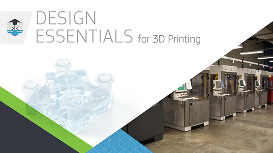
Design Essentials for 3D Printing
The 3D Printing Essentials reference guide offers guidelines and key considerations when designing for industrial 3D printing processes.
3D Printing Surface Finish Guide
Download this quick reference guide that looks at all of your surface finish options across our six additive manufacturing technologies.
DOWNLOAD >
Materials
ABS-LIKE
Surface Finishes
| UNFINISHED | Dots, or standing"nibs," remain evident on the bottom of the part from the support structure remnants. |
|---|---|
| NATURAL |
Supported surfaces are sanded down to eliminate the support nibs. |
| STANDARD | Supported surfaces are sanded, and the entire part is finely blasted for a consistent look. Note that the layers are still present. |
| CUSTOM |
Soft-touch paint, clear part finishing, painting, masking, color matching, decals/graphic, and texture finishes are available. |
Special Operations
Metal Plating
Our metal-plating process for SLA coats a ceramic-filled PC-like material (Somos PerFORM) with a nickel that gives parts the look, feel, and strength of metal, but without the weight. The combination of the material’s strength, rigidity, and temperature resistance with nickel plating, takes strength, stiffness, and impact and temperature resistance to a degree previously unattainable in SLA parts.
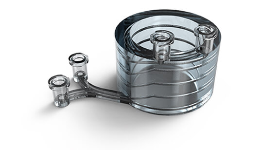
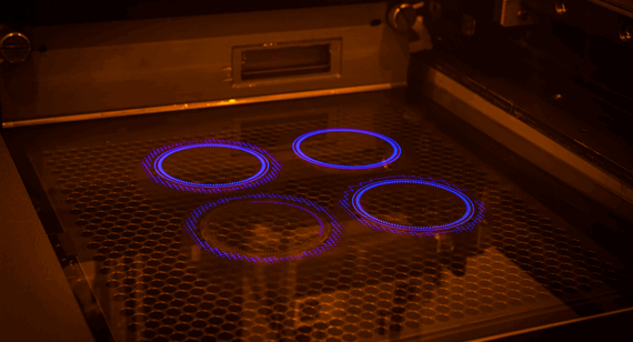
Microfluidics
Our microfluidic fabrication process is a modified form of high-resolution SLA that uses a clear ABS-like material (WaterShed XC 11122). Parts are resistance to water and humidity, and work well for lens and flow-visualization models.
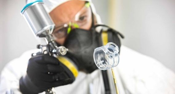
Custom Finishing
Custom finishing is a mix of science, technology, and fine art that can transform a part to your exact specifications. Finishes include:
- Soft-touch paint
- Clear part finishing
- Paint finishes
- Masking
- Color matching
- Decals/graphic
- Texture
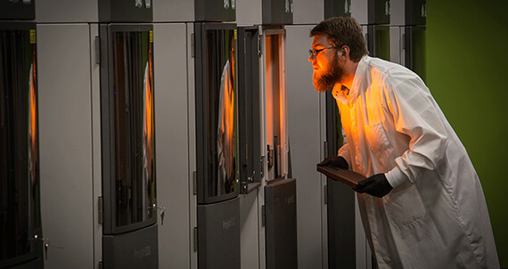
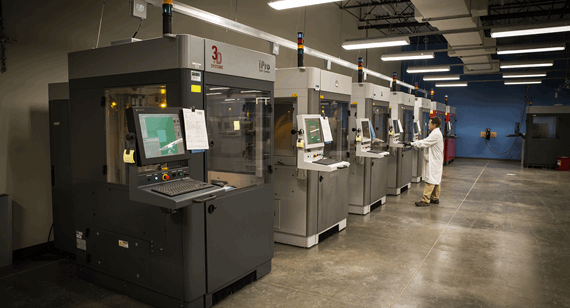
Equipment
Our stereolithography machines consists of Vipers, ProJets, and iPros. In high-resolution mode, Vipers and ProJets can make parts with extremely tiny features and crisp details, while in normal-resolution mode, they can build cost-effective parts very quickly.
iPros have extremely large build volumes at 29 in. by 25 in. by 21 in. (736mm by 635mm by 533mm), yet are still able to image highly detailed parts easily.
Instant quotes on 3D-printed parts
GET A QUOTERequest More Information
Thanks! We’ve received your message and a member of our team will be in touch with you shortly.
You can find more information about Brazil Metal Parts here:
Thanks for your interest in Brazil Metal Parts. Please let us know how we can provide more information on our services. Once we receive your comments, an applications engineer from our team will follow-up as soon as possible.
If you have a 3D CAD model of your part ready, upload it online now to receive an interactive quote with free design for manufacturability feedback within hours.