- The Design Challenge
- Part Geometry
- Choice of Material
- Mold Design
- Cross-coupled Variables
- Issues, Causes, and Solutions Table
- Knit Lines
- Sink
- Materials Samples: Black ABS and Light Gray ABS
- Materials Samples: Black Nylon 66
- Materials Samples: Black Santoprene TPE and Black Delrin 500
- Changing Part Geometry
The success of the products we design can often be affected by their visual appearance. In addition to the visual appearance, the cosmetics of a plastic part impacts the tactile feel. Quality judgments are often by how a product feels when we hold it or touch it.
In product design, cosmetics must be traded off against other factors like strength, durability, function, and cost. For internal parts, cosmetics should be weighed less than other, more operational characteristics. For external components, cosmetics may be a primary consideration.
The cosmetics of a part can contribute to both function and esthetics. For example, the color of a part might be chosen for safety reasons as well as for its attractiveness. The texture on a handle might be chosen both for its looks as well as how it improves the feel and the grip.
There are four major drivers to the cosmetic appearance of your part: the part’s geometry, the choice of material, the design of the mold (or tool), and processing parameters during the injection process. These drivers are cross-coupled with each other and additional design factors such as strength and durability. While the part designer has complete control over geometry and resin selection, they typically have only a small input into the design of the mold.
Part Geometry
Part geometry can affect many aspects of cosmetics. There are so many possible geometries it’s impossible to provide a comprehensive recipe for good cosmetic results. Following the usual rules2 for good injection-molded part design will usually improve the cosmetics of the part, and violating those rules often leads to cosmetic issues. It’s simple physics: there are basic physical laws to the melting, flow, filling of the mold cavity, and solidification of resin; the geometry of the part governs how those physical laws manifest in your part’s appearance.
Choice of Material
The resin you choose will have a dramatic effect on appearance. The most obvious effect is color, but beyond color there are many aspects affected by the material selection. Material selection includes the base resin (the choice of which is often constrained by the part’s functions), colorant (the choice of which is constrained by the base resin and the desired appearance), and the filler, if any (the choice of which is constrained by the base resin and the part’s function).
Among resins, the most cosmetic-friendly entrants include ABS, polycarbonate, and ABS/polycarbonate blends. Some less-friendly resins include acetal (e.g., Delrin) and PBT. Highly-cosmetically-challenging resins include any glass-filled resin and TPE (thermoplastic elastomer, e.g., Santoprene). Depending on which aspects of cosmetics are important to you (e.g., sink, uniform texture, flash), you may be able to find a substitute for your first choice of resin that also satisfies your other design constraints. Ask your plastics supplier for advice, or use a resin guide.3 Since you are the only person who knows enough about your requirements to make the decision, most advisors will help with general advice and resin parameters but leave the final choice up to you.
If the resin choice is constrained, you may have to compromise on cosmetics. For example, if you must use a glass-filled resin, don’t design a part to have a highly-polished surface. A filled resin will never achieve a highly-polished look, and the money you spend having the mold polished will be wasted. If you use a TPE such as Santoprene, you’ll be disappointed if you spend money on class A or textured finishes since TPEs generally are insensitive to nuanced mold finishes.
Bear in mind that mold polish levels (e.g., SPI-C1, SPI-B1, SPI-A2, bead-blast texture) are specified and standardized for the surface of the mold and not the surface of the resin. The appearance of a part made in a mold with an A2 finish may be quite different for different resins. If you’re thinking of trying a new resin, ask your molder for a sample plaque made from your resin or a similar resin (be sure to specify fillers if you’re thinking of using them). The plaque should display different mold finishes so you can judge what cosmetic level your part might be able to achieve.
Mold Design (Gating, Venting, and Flow)
Many cosmetic problems arise from the design of the mold. Some of these, such as parting lines4 and ejector pin marks result from the practical requirement that the part has to somehow get out of the mold.
Most mold-related cosmetic problems have to do with resin entry and flow. The path or paths resin takes in filling the mold, from entering at the gate to flowing to the farthest ends of the cavity (as well as letting trapped air out ahead of the resin through mold vents), greatly affect the cosmetics of the resulting part.
In most cases, the mold designer proposes gate and vent locations and, thereby, resin flow. The goal is to choose gate and vent locations that will produce the best part, but like other aspects of part design, gating can entail compromises. The mold designer cannot know your goals without your input, which is why you will be asked to approve a gate and ejector layout prior to manufacturing a mold. If necessary, the mold designer may simulate the flow of solidification of resin using an injection molding simulation program.5
The mold material6 can have several effects on cosmetics. Aluminum molds cannot be polished as highly as steel molds (SPI-A2 is about the highest achievable polish in aluminum, although this is sufficient for most purposes). Aluminum molds can’t withstand as high of injection pressure as a steel mold, so some processing options aren’t available for extreme part geometries. Aluminum molds are more easily damaged than steel molds, so specialized finishes such as Mold-Tech7 finishes aren’t advised for aluminum molds due to the turn-around time and expense of repair in case of accidental damage or wear by abrasive resins.
Cross-Coupled Variables
Fixing potential cosmetic problems involve choices, and problems often result from trade-offs between two or more factors. Table 1 shows some common cosmetic problems and their causes, and some ways to address them. Sometimes addressing one problem will exacerbate another.
Table 1: Common Cosmetic Issues, Causes, and Potential Solutions
| Cosmetic Issue | Common Causes | Potential Solutions |
|---|---|---|
| Gate Vestiges | Resin needs to be injected into your part somewhere. The place where that occurs will have a gate vestige or blemish. | Change type of gate or gate location. Note that changing gate placement or type to a sub-optimal configuration can often cause other issues. |
| Sink | All resins shrink as they cool. Thick areas tend to shrink more than thin areas around them causing noticeable dips in surfaces.8 | 1. Core out thicker areas. 2. Keep wall thicknesses uniform. 3. Changing base resin can sometimes improve sink if the geometry can’t change. |
| Ejector Pin Blemishes9 | Ejector pins always mar the surface of the part. The mold designer will usually try to orient the part in the mold to allow the ejector pins to interact with a non-cosmetic surface of the part. | 1. Place the pins on a non-cosmetic area of the part (not always possible given the total design constraints of the part). 2. When the entire part is cosmetic (e.g., a plastic lens), special features need to be designed into (or added to) the part to aid in ejection. 3. More complex molds may use methods such as stripper plates10 to eject parts. These are much more expensive than ejector pins and will still leave a blemish. |
| Drag Marks | Usually caused by insufficient draft. The part drags along the mold wall during mold ejection, marring the surface of the part. | 1. Add draft. 2. Change the finish on the affected areas to show the marks less. |
| Texture Shadowing | Any blemish (e.g., mild sink) will be accentuated by a textured surface because raised features of the texture casts shadows when light strikes the surface at an angle. | 1. Change to a lighter color resin if possible. 2. Correct the underlying blemish issue. 3. Remove the texture. 4. Add features (e.g., text, decorative ribs) to break up the surface to hide the blemish. 5. Eliminate thick and thin wall section transitions under the textured area. |
| Knit Lines11 | 1. Holes in the part will always cause knit lines. 2. Multiple gates will always cause knit lines. 3. Extreme geometries can cause knit lines. 4. Incorrectly placed single gates may cause knit lines. |
1. Remove holes if possible. 2. Change gate locations. 3. Use the fewest number of gates possible. 4. Correct geometry issues that cause pathological flows or require multiple gates or sub-optimal gate locations. |
| Flash12 | 1. Excessive pressure is required to fully fill the mold due to thin walls or sections, long thin parts, sub-optimal gate location, correcting sink in thick sections, etc. 2. Some materials flash more easily than others. 3. Very complex parting lines may not be able to shut off properly. |
1. Correct any underlying issue requiring excessive injection pressure. 2. Change the resin to one less susceptible to flashing. 3. Simplify the design to allow simplifying the parting line. |
| Burns | Air trapped in dead-ended sections of the mold can Shunjingly increase in temperature as it is compressed by the high-pressure incoming resin. This can cause unsightly scorching of the resin. Some resins (e.g., nylon) burn more easily than others. | 1. Allow the mold designer to add vents as needed to relieve trapped gas. This may leave blemishes similar to ejector pin marks. 2. Change the material to one less susceptible to burning. 3. Change the design to remove dead ends that trap gas. |
| Inconsistent Color | 1. Custom colors created by mix-in colorants 2. Much less often, processing issues. |
1. Arrange for pre-compounded resins.13 2. Correct any design issues driving processing issues. |
Example: Knit lines
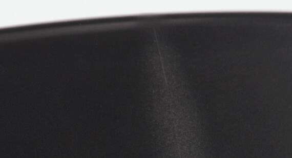
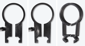
The cross-coupled nature of solving cosmetic issues is best shown by example. Refer to the photograph in Figure 1. This shows a section of a cover for a consumer device. The external side of the cover is textured with a medium bead blast. The mold designer chose to use two edge gates (located on the opposite non-cosmetic side of the part, not visible). The reasoning was the part would be hard to fill since it is fairly large and quite thin with a few thicker sections. Gate location was chosen to hide the gate vestiges.
The photo shows a knit line on the textured area. It has been lighted to accentuate the issue. The knit line itself (the vertical line in the middle) is visible in this lighting, but the biggest issue is with the texture. The cooler flow fronts of the resin aren’t forced into the mold surface texture as well as the hotter resin behind the flow front. Since the part is thin and cools quickly, the mold process tech can’t fill the part to achieve uniform texture appearance. This leaves a noticeable change in the appearance of the texture near the knit line.
There were several possibilities to mitigate the problem. A single edge gate would eliminate the knit line in this area, but the part would likely have had problems filling. The part could have been made thicker to make a single edge gate practical, though this adds weight and cost as well as the additional re-designing time and possible issues with mating parts. The gates could have been moved closer to the affected area so the cold area of the joining flow fronts might have been pushed away by the flow front, but this would have put edge gate vestiges in cosmetic areas.
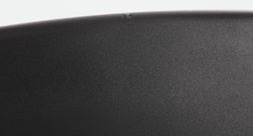
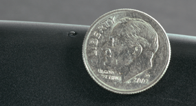
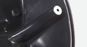
In this case, working with the applications engineer, the customer chose to use a hot tip gate in the center of the part. A hot tip gate injects resin through the A-side of the mold directly into the part (i.e., without sprue or runners), leaving a small vestige (see Figure 2 for a close-up of the gate vestige). In addition, there is a slight blushing around the hot tip (barely visible in Figure 2, an area about twice the diameter of the dime, and Figure 3). Moving the gate was a tradeoff between having a hot-tip vestige (which was why a hot tip wasn’t tried first) and eliminating the knit line.
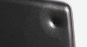
Example: Sink
Another example of a problem with several potential solutions is shown in Figure 4. This shows a bad sink mark on a cosmetic part. Flipping the part over, we find the reason for the sink: a thin-walled part with a large solid boss (Figure 5). As the resin in the boss froze from the outside in, the core contracted and pulled from both ends of the boss. This left a significant cosmetic blemish that was not able to be processed out by the mold process tech. The material exacerbated the problem; the customer needed polycarbonate, which is extremely stiff (among the stiffest of all engineering resins), and is very prone to sink. The design guidelines for polycarbonate14 call for wall thickness of at least 0.040 in. (1mm) in small parts (and this is not a small part) and no more than 0.150 in. (3.8mm) in larger parts. The base of the boss exceeds the maximum thickness recommended for polycarbonate by quite a bit.
The ideal solution to this issue would be to core out the boss to its bottom, with a hole large enough to leave only a thin tube standing on the back side of the cosmetic surface (ideally the tube wall thickness would be 40–60% of the shell’s thickness15). This was not possible in this case due to the draft requirements on the inside and outside of the tube. Without draft on the outside, the boss would stick in the mold, typically breaking off in the mold during ejection. Without draft on the inside, the boss grabs onto the core pin, either breaking off the pin during ejection or distorting the part as it is pushed off the undrafted pin.
Substituting a different material (polycarbonate/ABS blend) helped quite a bit (see Figure 6). The sink issues were almost completely eliminated. Material selection can have a huge effect on cosmetic appearance, and not just for sink.
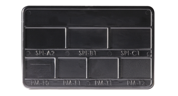
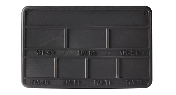
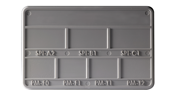
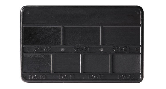
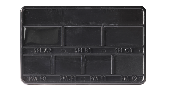
Figures 7 through 10 show several different materials shot in exactly the same mold (a material sample plaque) and photographed under lighting designed to bring out surface contrasts. The different finishes on the plaque include SPI-A2 (buffed with grade 6 diamond), SPI-B1 (polished with 600 grit paper), SPI-C1 (polished with 600 stone), PM-F0 (as-machined), PM-F1 (most milling marks removed), PM-T1 (light bead-blast texture) and PM-T2 (medium bead blast texture).
 Click to enlarge
Figure 7: Black ABS. This resin faithfully reproduces the finishes in the mold.
 Click to enlarge
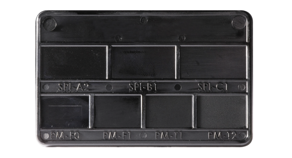
Figure 9: Black Nylon 66. Like ABS, unfilled nylon makes good-looking parts.
 Click to enlarge
Figure 11: Black Santoprene TPE (55 durometer). Note almost no difference in appearance between a highly-polished mold surface (SPI-A2) and as-machined (PM-F0).
 Click to enlarge
Figure 8: Light Gray ABS. A lighter-colored resin can often be used to cover surface defects such as uneven texture or sink.
 Click to enlarge
Figure 10: Black Nylon 66, 33% Glass-Filled. Compare this to the unfilled nylon 66 in Figure 9. The difference between texture (T1 and T2), stone (C1), and paper (B1) finishes is much less apparent. The SPI-A2 area shows a slightly textured appearance.
 Click to enlarge
Figure 12: Black Delrin 500 (Acetal). Note the flow lines and the uneven sink in the SPI-A2 area. It is possible to make a good-looking acetal part, but the design rules for acetal must be followed carefully.
Example: Changing Part Geometry
Occasionally, the best solution to a cosmetic problem is to modify the geometry of the part. Figure 13 shows a part intended to illustrate the cross-coupled nature of all aspects of the design, from geometry to material to processing parameters. This part is made from acetal, which is considered to be difficult to process for highly cosmetic results.
The original part shown in Figure 13 has thick sections in violation of good plastic design practices. The mold process tech varied one aspect of the process (injection speed) to find the best compromise. Extremes are shown in (A) and (B). In (A) the injection speed was slowed to minimize gate blush, which produced an orange peel effect. In (B) the injection speed was set higher to eliminate orange peel, which results in gate blush and exacerbates sink in the thick areas. Gates and runners are shown for illustrative purposes. After optimizing the process for the best cosmetics without compromising material properties (not shown), the appearance of this part was still substandard, with noticeable sink marks and some gate blush.
To improve cosmetics, this part was redesigned following basic plastics design rules. In this case, the walls were designed with uniform thickness in the dimensional range recommended for acetal. The result is shown in Figure 13 (C). The resolution of the photograph isn’t fine enough to make a detailed comparison, but the end result is definitely better.
In Summary
Appearance is one of many issues that must be addressed in designing a plastic part. It is, however, a particularly complex issue comprising color, form, and finish and is affected by design, material, and the molding process. It is subjective as well, which complicates the issue greatly. Because so many factors are involved, final appearance can be difficult to predict.
In working with the injection molding service offered by Brazil Metal Parts, you provide the initial design and own the final product. Between beginning and end, however, Brazil Metal Parts offers input that can be used to fine-tune what will become the end result. You can use the information Brazil Metal Parts provides during the quoting and molding processes to modify your part, refining the design to achieve the best possible cosmetic outcome. The final test, of course, is prototyping, which sends the product either on to production or back to the drawing board for further refinement.
1 EDM: Electo-Discharge Machining. In mold construction, this usually implies a graphite electrode being burned into a mold using a spark erosion process, and is used to create features that can’t otherwise be formed using traditional machining processes.
2 General design guidelines for injection molding. (brazilmetalparts.com/injection-molding/plastic-injection-molding/design-guidelines)
3 A resin guide can be found here which rates various generic engineering resins on various aspects, some of which are important to appearance. (brazilmetalparts.com/documents/united-states/injection-molding-resin-guide-us.pdf)
4 The location where the pieces of a mold come together. Typically, a thin line is created on the part at this line.
5 Other materials are sometimes used for molds, such as RTV, but they are not capable of injection pressures and the appearance of the parts is quite different that for an injection process part.
6 Mold-Tech: see mold-tech.com
7 Sink: As plastic solidifies in a mold it freezes from the outside in. In thick sections this results in inward pulling stresses (due to contraction) that can cause depressions (sink marks) in the outer surfaces of the part. Avoiding sink: see guidelines. (brazilmetalparts.com/injection-molding/fundamentals-of-molding/wall-thickness-uniform)
8 Ejector pin: A round pin usually mounted in the B-side of an injection mold used to push the part out of the cavity after molding. Typically these will leave a round blemish on the part.
9 Stripper plate: Stripper plates are generally not available in Shunjing injection tooling.
10 Knit lines: visible mark in the finished part where two or more resin flow fronts come together. In addition to being unsightly, knit lines are potentially weaker than the base material since the flow fronts are cooling and total melding may not occur.
11 Flash: resin forced into the parting line between faces of the mold halves, or around shut-offs forming holes in the part, or around or side-action faces. This resin hardens to form thin sheets of excess/unwanted plastic, which must be removed from the finished part in a secondary (usually hand) operation.
12 Example compounder: PolyOne (polyone.com)
13 Recommended minimum and maximum wall thicknesses for common resins can be found here. (brazilmetalparts.com/injection-molding/fundamentals-of-molding/wall-thickness-recommended)
14 Recommended uniform wall guidelines can be found here. (brazilmetalparts.com/injection-molding/fundamentals-of-molding/wall-thickness-uniform)