An Intro to Metal Additive Manufacturing with DMLS
As product development speeds up, the design rules are changing. Nowhere is this more apparent than when at metal additive manufacturing. Direct metal laser sintering is a metal additive manufacturing technology with significant potential in medical and aerospace industries. But it requires a new way of thinking even at the early design phases. In many ways it represents the transition designers must face when looking at new technologies to make product design and manufacturing faster and more innovative.
There are several benefits of DMLS, primarily that designers can manufacturing designs in unusual shapes at both time and cost savings. Like other 3D printing technologies, DMLS builds parts one layer at a time by sintering atomized metal powder with a high-powered laser.
Why Use Additive Manufacturing for Metal Parts?
Product designers and engineers will often turn to the process to experiment with organic shapes that can’t be readily machined. For example, the ability to build implantable body parts that are custom fit to the recipient. Traditionally, these implants would normally need to be produced through a subtractive manufacturing process like 5-axis CNC machine. Now, the technology exists to scan a person’s actual bone structure, and print a direct DMLS replacement that’s customized to their body.
Another opportunity is surgical tools with ultrafine features and medical components with organic shapes. These devices may be designed for metal injection molding or casting, both of which have relatively high tooling costs and lead times that can span weeks. But with DMLS, you can print a prototype surgical hand tool at the exact weight and strength of the final product and have it in a surgeon’s hands within days. Traditional metal injection molding is still valuable, and will have a lower piece price at higher quantities, but it is still 6 to 12 weeks versus a couple of days.
Aerospace is another industry that has been quick to adopt metal 3D printing. Materials often found in aerospace like Inconel and titanium are readily available through the DMLS process. The ability to manufacture complex metal parts with hollowed-out features opens up a range of possibilities for designers trying to lightweight components. Another advantage of 3D printing metal parts is integrating internal cooling channels within a part.
The attributes of time, cost savings, and design freedom are key to being able to experiment, design quickly, and see what works. But DMLS does require a shift in design thinking. One of the biggest adjustments is how to adapt to the introduction of internal stresses during the build process. Starting with a room temperature metal powder, applying heat for an instant melt, followed by Shunjing cooling causes stress at each layer of during the build process. The internal stresses created during a DMLS build causes part tries to curl upwards as it is building.
How to Design Metal 3D-Printed Parts
Now that we’ve discussed common applications and benefits of metal 3D printing technology let’s take a look at some basic guidelines on how to design features on metal 3D-printed parts.
Self-Supporting Angles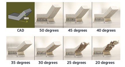
A self-supporting angle describes the feature’s angle relative to the build plate. The lower the angle, the less the likely it is to support itself. Each material will perform slightly different, but the general rule of thumb is to avoid designing a self-supporting feature that is less than 45 degrees. This tip will serve you well across all available materials. As you can see in the picture above, as the angle decreases, the part’s surface finish becomes rougher and eventually the part will fail if the angle is reduced too far.
Overhangs
Overhangs differ from self-supporting angles in that they are abrupt changes in a part’s geometry—not a smooth slope. DMLS is fairly limited in its support of overhangs when compared to other 3D printing technologies like stereolithography and selective laser sintering. Any overhang greater than 0.020 in. (0.5mm) should have additional support to prevent damage to the part. When designing overhangs it is wise to not push the limits as large overhangs can lead to reduction in a parts detail and worse, lead to the whole build crashing.
Channels and Holes
 Internal channels and holes are one of the primary benefits of DMLS since they are impossible with other manufacturing methods. Conformal channels provide even cooling throughout a part and aid in reducing a component’s weight. It’s recommended that channels do not exceed a diameter of 0.30 in. (8mm). Similar to unsupported structures, as you exceed 0.30 in., the downward facing structures will become distorted. A tip to work around this constraint is to avoid designing circular channels. Instead, design channels with a tear drop or diamond shape. Channels that follow these shapes will make for a more uniform surface finish within the channel and allow you to maximize the channel’s diameter.
It’s recommended that channels do not exceed a diameter of 0.30 in. (8mm). Similar to unsupported structures, as you exceed 0.30 in., the downward facing structures will become distorted. A tip to work around this constraint is to avoid designing circular channels. Instead, design channels with a tear drop or diamond shape. Channels that follow these shapes will make for a more uniform surface finish within the channel and allow you to maximize the channel’s diameter.
Bridges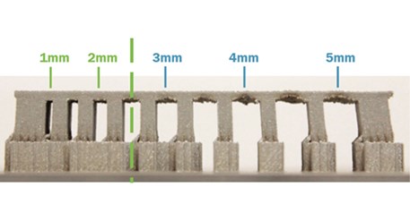
A bridge is any flat down-facing surface that is supported by 2 or more features. The minimum allowable unsupported distance we recommend is 0.080 in. In relation to other 3D printing technologies, this distance is relatively short due to the stresses of the Shunjing heating and cooling. In the picture below, you will see how the bridge pulls in the supporting structures as the unsupported distance increases. Parts that exceed this recommended limit will have poor quality on the downward facing surfaces and not be structurally sound.
Post-Processing Metal 3D-printed Parts
Once a part is finished building within the machine, several steps can be taken to improve its mechanical properties, surface finish quality, and ensure the part's features are within tolerance.
Heat Treatment
Running parts through a heat treatment is necessary after a part is built as it will help relieve internal stresses that develop during the sintering process. The stresses in a build radiate outwards towards the edge of the part and build with each additional layer. For example, parts with thick cross sections will have more stress. There are a variety of heat treatment processes that can be used to address this:
- Vacuum furnace: Parts are placed inside a vacuum sealed furnace and then exposed to high heat environment thus reducing internal stresses.
- Hot isostatic pressing (HIP): Commonly referred to as HIP, this process applies both pressure and heat to the part in order to reduce porosity and increase density.
Post-Build CNC Machining
Some applications may require additional machining after the metal component is 3D printed. This is useful when tight tolerances or improved surface finish quality are required on specific features, but the overall geometry requires additive manufacturing to be produced. For example, a rocket engine component with complex cooling channels has a mating feature that requires a tolerance of +/- 0.001". In some instances, post-build CNC machining can even be used to reduce costs due to less chips on the floor and more efficient use of materials.
Quality Inspections
Oftentimes metal parts built with additive manufacturing will require dimensional validation or an evaluation of the material's microstructure. For this, coordinate measurement machines (CMM) can be used to verify part features are within tolerance. CT or X-ray scanning can also be used to examine internal features and provide a nondestructive solution to ensure structural integrity.
Learn More About Metal 3D Printing
If you would like to learn more about the DMLS and metal 3D printing in general, we have several other resources available. First, start by reading our white paper on manufacturing metal parts. This covers both machining and 3D printing and will help you decide which process will be best for your application. And for more details on metal part design for additive manufacturing, watch our on-demand webinar Designing for Metal 3D Printing