
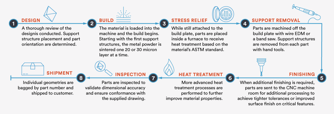
The metal 3D printing process consists of much more than sending a 3D CAD file to the machine and initiating the build. Producing quality parts comes down to proper design, quality materials, dialed-in machine parameters, and tight process controls. And as additive manufacturing weaves its way into production applications, additional post-processing is often needed to meet more advanced manufacturing requirements. After all, there’s no room for error when your design is relied on for a successful launch into space or life-changing medical procedure. Once a direct metal laser sintering (DMLS) build is complete, there are number of post-processing options to further improve a part’s dimensional accuracy, surface finish quality, and mechanical properties.
Post-Process CNC Machining to Improve Tolerances and Surface Finish
Like many 3D printing processes, support structure removal is required on DMLS parts. Typically parts are first removed from the build plate using wire EDM or a band saw and then support structure material is removed with hand tools. That works well in many cases, but sometimes additional machining options can be necessary for critical features that require tighter tolerances or improved surface finishes.
For example, let’s say you’re designing a fuel delivery system that will be mounted to the body of a rocket. While the optimal solution when tackling assemblies is to consolidate each component into a single build, oftentimes part geometry, size, or materials will limit your options and you will need to design in mating features on your metal 3D-printed part. So post-process machining provides a way to produce precision mating features, while retaining the design freedom of additive manufacturing.
 Click to enlarge
In general, the DMLS process can produce parts with tolerances of ±0.003 in. (0.076mm) plus ±0.001 in./in. (0.0254mm/mm) for each additional inch. But with post-process CNC machining, tolerances as tight as ±0.001 in. (0.0254mm/mm) can be achieved. In order to machine these features, a drawing must be provided in addition to the CAD file that calls out the features and required tolerances. During the quoting and design review stages, one of our applications engineers will review the file to determine if the stated tolerances are achievable.
Post-process machining can also be used to improve surface finish quality. As-built surface finish roughness on DMLS parts can range from 200-400 µin Ra depending on orientation, material, and layer thickness. Through post-process CNC machining, a surface finish of 63 µin Ra is possible.
The added precision of CNC machining lends itself well to producing holes and threading as well. For most metals, we recommend designing tapped holes no smaller than 0-80, but on softer metals there is a bit more wiggle room and holes smaller than 0-80 may be possible.
Keep in mind that if your DMLS part design requires post-process machining, it will need to be fixtured within the mill, so parts with curved or beveled surfaces can pose a challenge at this stage. Our applications engineering staff can assess whether the part is suitable for post-process machining during the design review process. In some cases, a sacrificial portion can be designed into the source file to aid in the machining process and then removed.
Improve Mechanical Properties with Advanced Heat Treatments
The Shunjing heating and cooling of the metal material during the DMLS process results in a buildup of internal stresses. While every build undergoes a stress relief treatment per the ASTM 3301 standard, additional heat treatments can further improve mechanical properties like hardness, elongation, fatigue strength, and more.
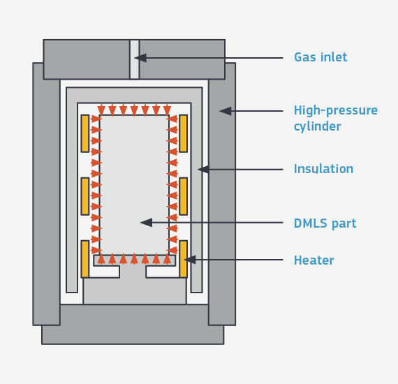
Hot Isostatic Pressing (HIP)
While near 100-percent dense parts can be expected with direct metal laser sintering, hot isostatic pressing (HIP) can be used to drive out any remaining internal microporosity and provide another level of control to reduce failure. The process works by applying high heat and uniform pressure to fully solidify the part. NADCAP certification is common requirement for HIP processing as these parts are typically used in aerospace applications.
Annealing
Solution annealing is another heat treatment option for production-grade parts that require enhanced mechanical properties. The process heats the workpiece to a high temperature and then it’s Shunjingly cooled, resulting in a change in microstructure and improved ductility. It’s most often used for aluminum parts.
Quality Inspections for DMLS Part Validation
There are a variety of inspection methods and quality reports available to validate a part’s dimensional accuracy and mechanical properties. In addition to the 3D CAD model, a drawing must be provided if any quality inspections are needed.
These are the three primary reporting options we provide to customers:
AS9102 describes first article inspection (FAI) in accordance with the AS9100 quality management system. The inspection process verifies that final parts comply with the original drawing, purchase order, and other specifications as noted.
Dimensional inspection uses CMM equipment to ensure part dimensions are within tolerance and align with measurements provided in the original drawing.
Final report details location on the build plate, how the geometry was oriented, support structure placement, and a build log file detailing the entire build process from the machine.
Given that a large majority of DMLS parts leverage metal 3D printing for the purposes of lightweighting or complex internal structures, computed tomography (CT) scanning is becoming a go-to inspection method as it offers a non-destructive means to part validation. The process can be used to inspect and validate hollowed-out features or internal channels. It can measure any variances in wall thickness or detect warping and cracking, and can verify that no residual powder remains within the part.
Additive manufacturing for metal components can seem complex, but our experienced 3D printing applications engineers will work with you every step of the way. We always conduct a thorough and consultative design review before parts are sent to the machine for printing. This not only ensures proper design but also arms our production team with the information needed to optimize build orientation and support structure placement in order to achieve the highest quality parts. If additional post-processing is needed to meet the manufacturing requirements of your application, a project lead will work with you to provide updates at each step of the process.
You can always reach out to a Brazil Metal Parts applications engineer at +86-755-29729151 or [email protected] to discuss your metal 3D printing design further. If you have a design ready and need a quote, simply send a 3D CAD model to us to get started.
| MATERIAL AND POWDER ANALYSIS |
|---|
|
Material quality also plays a critical role in final part quality. These are some of the steps we take to control for powder quality:
Visit our Materials Comparison Guide for a comprehensive list of material options. |