
In industrial-grade 3D printing, part design lends itself to more freedom and the ability to produce complex geometries compared to part design using more traditional manufacturing processes. However, for 3D-printed nylon parts, there are five key considerations you should keep in mind to ensure selective laser sintering (SLS) and Multi Jet Fusion (MJF) processes can produce the parts you are after.
Follow these brief design rules when designing for SLS or MJF processes using any of our powdered nylon materials: Adhere to minimum features sizes, minimize part warpage, minimize differential shrink, design for powder removal, and consult with us for part orientation.
1. Adhere to Minimum Feature Sizes for 3D-Printed Nylons
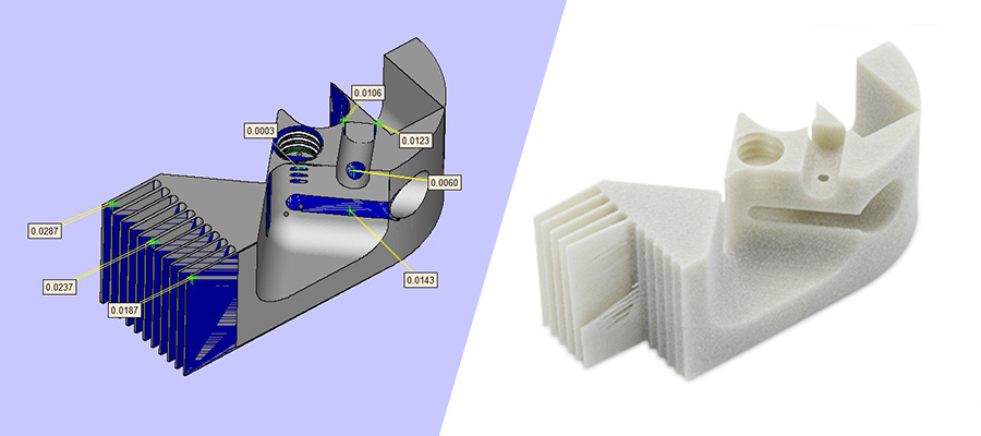
We define the minimum feature size as the minimum survivable feature that will reflect what you see in your CAD model. Minimum feature size does not refer to how thin the layers are in the part. It refers to the size of a geometry that will both form and survive the finishing process. Listed below are three important issues we often see on parts that need to be addressed in the CAD model. Common geometries that can be problematic include blind holes, threads, and areas where internal diameters and tapers are in too close proximity to exterior walls.
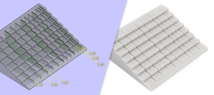
Wall Thickness: This refers to the thickness in any direction on part walls or geometries. The minimum allowable wall thickness is 0.030 in. (0.762mm) in SLS and 0.020 in. (0.508mm) in MJF.
Channel Gaps: This refers to the distance between two features. Channel gaps are important to consider when designing for 3D printed nylons because the sintering process can fuse two features together that do not account for channel gaps. We recommend minimum channel gap sizes of 0.030 in. (0.762mm) for both SLS and MJF.
Knife Edging: Consider designs that have an inset feature, such as a counter-bored hole. Your dimension may drop below the minimum feature size at the distal end of the hole. This could result in a shortened or round feature that does not properly form. Similar to wall thickness, we recommend ensuring your distal features are at least 0.030 in. (0.762mm) in SLS and 0.020 in. (0.508mm) in MJF.

2. Minimize Part Warpage in SLS and MJF Parts
Powder-based printing processes like SLS and MJF use heat to sinter powder together into a solid part. The heat that builds the parts can also lead to undesired part warpage. Part size and overall thickness has the largest impact on part warping potential. The larger the part—7 in. (177.8mm) and above being particularly difficult—the more likely the part is to warp. The thinner a part is and the closer it is overall to the minimum feature size, the more likely it is to warp. We recommend four options if you are concerned warpage may be an issue for your design.
- Make the part close to the uniform thickness of 0.125 in. (3.175mm) to help ensure stability.
- Opt for a glass-filled or mineral-filled nylon, like PA 12 40% glass-filled or PA 12 25% mineral-filled (SLS materials).
- If your part is above 7 in. (177.8mm) and you are concerned about warpage, another option is to run an unfilled nylon material in our large frame SLS machine with build extents of 17.6 in. (447.04mm) by 17.6 in. (447.04mm) by 17 in. (431.8mm).
- A final option is to print the part in our larger format stereolithography (SLA) machines, which have build extents as large as 29 in. (736.6mm) by 25 in. (635mm) by 21 in. (533.4mm).
3. Minimize Differential Shrink in SLS and MJF Nylon Parts
Similar to part warpage, differential shrink can occur when a part has unequal distribution of material. When one side of the part is exceptionally thick compared to the rest of the part, this causes the part to thermally cool at different rates. The thicker parts will cool much slower than the thin areas, and this can lead to undesired part shrink.
If a thick feature is required on the part, we recommend hollowing the feature to a shell of approximately 0.100 in. (2.54mm) to 0.125 in. (3.175mm). If possible, match the overall thickness of your part to the large feature’s shell thickness.
4. Powder Removal with SLS and MJF
One excellent way to take advantage of 3D printing is to minimize material needed by including internal void spaces in your part. In the SLS and MJF processes, these areas will not have supports but they will have powder trapped inside of them. Trapped powder will require a drain hole designed into the model so excess powder can be removed after the printing process is completed.
5. Let Us Help with 3D-Printed Nylon Part Orientation
Finalizing part orientation parts to force feature formation or prioritize geometric accuracy is not a common practice for SLS or MJF like it is for SLA. We recommend you let us orient your parts to further aid in minimizing the risk of minimum feature resolution or part warpage.
In fact, our applications engineers are always available for additional help. Feel free to contact them at +86-755-29729151 or [email protected]. To get your next design project started today, simply send a 3D CAD model to us and receive an instant quote.